"Quick & Dirty" Marx generator
Update May 2003 - Marx Three is now up & running
Do you like the idea of tesla coils and other high-voltage sparking stuff, but don't have the time, money or patience to build something that elaborate? Here's a fun little project that can make big, fat, noisy sparks at least 2 inches long, and can be built very quickly and cheaply.
The Marx generator consists of an array of resistors, capacitors and spark gaps arranged as follows:
The capacitors, C, are charged up in parallel via the 1M (one megohm) resistors, so they each become charged to the input voltage. When first (leftmost) spark gaps breaks down (sparks), the voltage across the next increases, causing it to break down, and so on for all the other gaps. When all gaps have broken down, the low impedance of the ionised air in the sparks effectively connects all the charged capacitors in series, multiplying the input voltage by the number of capacitors. The ionised air path has sufficiently low resistance that the charge resistors don't have any significant effect.
Rb has a ballasting effect. This is needed to avois a continuous arc forming across the first gap after it fires - this prevents further firing. The value will depend on the type of power supply used - values around 1M usually about right. High values will reduce the maximum spark repetition rate, so you may be able to get more 'bangs per second' by reducing Rb.
Although it is possible to make a Marx generator with just an array of resistors,
capacitors and spark gaps, it can be hard to make it fire reliably, as it will
depend on the breakdown voltage of the spark gaps, and there can be a fine line between
not firing and firing before all the capacitors are fully charged. One crude solution is
to initate the breakdown of the first gap mechanically, e.g. by waving a (suitably
insulated!) screwdriver between the electrodes.
A more elegent approach is to add a trigger circuit, like the one shown above. This
consists of a relaxation oscillator to generate high voltage trigger impulses to initiate
the spark at the first gap. V is a small xenon flashtube - preferably the linear type (as
opposed to the U shaped ones used in larger strobes). Tt is a trigger transformer of the
type used on camera flashes and strobes. Rt and Ct determine the operating frequency -
typically one pulse every second or two. I used two of the 4.7nF caps for Ct, and five 33M
resistors in series for Rt. Note that the xenon tube and trigger transformer are used in
the opposite way to their normal application - here the tube breaks down due to the high
voltage, discharging Ct into the coil to create the trigger spark. The output wire from Tt
(The one that would be connected to the trigger electrode in the original flash
application) is placed a couple of mm from the first spark gap, as shown above, so a spark
will jump from it when triggered. I found that the cheap coil I used tended to
die after several minutes' operation, so something with stronger insulation would be
preferable.
Component choice
I based the component values on what I had available, and there is plenty of scope for
experimentation here. If in doubt, try building just a couple of stages first to see how
well the parts you use will work.
The most important thing is to make sure that the components are suitable for the input
voltage used. This includes the resistors - normal 1/8 or 1/4 watt carbon or metal
film resistors are NOT suitable for high voltage uses like this. Larger (2 watt) carbon
resistors, or high-voltage metal glaze resistors must be used. Alternatively several
standard resistors can be used in series, calculated such that each resistor sees no more
than its noltage rating (typically about 500V). For example, ten 100K 1/4 watt resistors
could be used in place of each 1M HV resistor. The value of the 1M resistors is not too
critical - higher values will increase recharge time, lower values will increase losses as
some of the spark discharge leaks back through the resistor chain, especially with lower
value capacitors.
Capacitors should ideally be ceramic types, as these are best suited to the fast pulses in a Marx generator - polypropylene pulse-rated caps would probably also work well, but are more expensive, and harder to find with high voltage ratings. Use the highest voltage types you can find - 6.3KV types are readily available from most component suppliers, and values up to 15KV are not too hard to find. I used 4.7nF 4KV parts as I'd recently picked up a big bag of them very cheaply at a radio rally (hamfest). Larger values will give fatter sparks, but take longer to recharge! You can often run these in excess of their rated voltage, but obviously this runs an increased failure risk.
An input voltage of about 4-8KV is recommended. Above this, many problems will detract from the 'quick and dirty' approach, requiring much greater care in construction to reduce corona losses from sharp edges, multiple series resistors would be needed, and the capacitors will be harder to find. The high impedance of the charging network mean that corona losses can significantly degrade performance above about 5-6KV unless care is taken to avoid any sharp edges - e.g. by filing the wire ends and joints smooth..
Power supply
This design requires a low-current source of high voltage DC in the range 4-8KV (polarity is unimportant). Small, low-current HV supplies from things like ionisers, photocopiers and laser printers should be suitable. I used a surplus 5KV 2mA photomultiplier supply.
The number of stages you use will determine the output voltage, and hence spark length. There will be upper limits on the practical number of stages, due to charging time and the speed at which the discharge propagates along the gaps. I ran out of resistors before I found the limit!
Close of spark gaps and general construction.
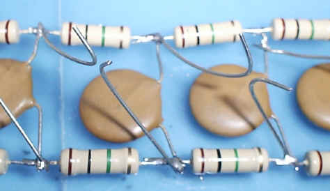
The spark gaps are simply formed from thick tinned-copper wire, as shown above. It is important that the gaps are curved, and the sharp ends of the wire are bent away as shown - this avoids corona loss and premature breakdown. The wire used should be at least 1.5mm dia. The output gap however should use fairly sharp points for maximum spark length. Take care to avoid spark discharge from the ground electrode to the resistors or capacitors near the 'hot' end, as these discharges could break down the components' insulation.
Gaps should be initially set to about 1.5mm. Some adjustment may be required - if the generator doesn't fire, one or more gaps are probably too far apart. If gaps are too close, especially near the supply end, you may see a continuous arc forming, preventing further operation. Increasing the gap on the first (and possibly second) stage may reduce the tendancy to arc. Increasing the ballast resistor Rb also helps, at the expense of slower recharge time. Continuous arcing can also be significantly reduced by passing some airflow, e.g. from a small fan, between the gaps.
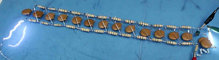
As can be seen from the photo, a very crude 'Christmas-tree' type construction can be used, the components being simply soldered together - of course a neater assembly technique could be used, but bear in mind that whatever you build it on must withstand the full discharge voltage - Perspex (Acrylic/Plexi) or polycarbonate (Lexan) is ideal. If doing a simple 'lash-up', at least place it on a plastic sheet to avoid discharging to the table/banch - wood is not a good insulator at these voltages! Avoid sharp edges on any of the connections (e.g. don't use metal screws), as this can cause corona losses, reducing output significantly.
The size of sparks at the output gap will depend on the input voltage and number of stages - start with it set to about half an inch, and gradually increase it (careful!) until you no longer get sparks.
More on Marx generators here
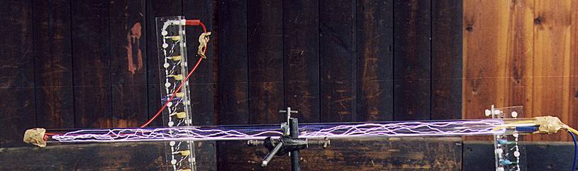
"Marx Two"
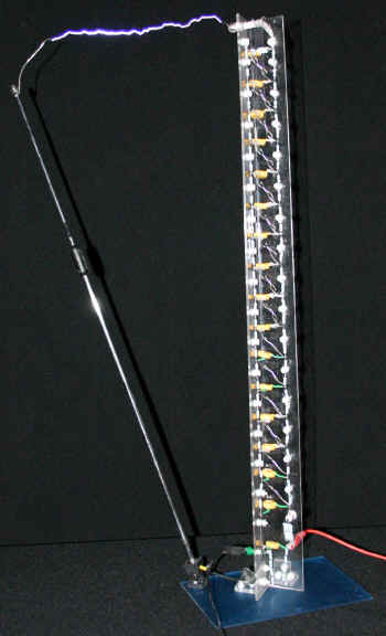
 This is a development from the 'quick & dirty' device
above. The construction is basically similar, but it has better (i.e. some!) mechanical
support, being mounted on a strip of Perspex (=Acrylic/Plexi) which was heat-folded to a
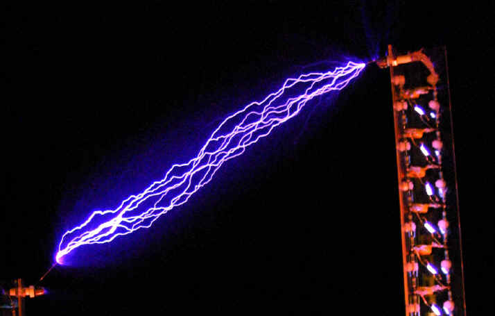
'V' section for rigidity. It produces sparks up to 9" long from an input of about
16KVDC.
This is a development from the 'quick & dirty' device
above. The construction is basically similar, but it has better (i.e. some!) mechanical
support, being mounted on a strip of Perspex (=Acrylic/Plexi) which was heat-folded to a
'V' section for rigidity. It produces sparks up to 9" long from an input of about
16KVDC.
To allow a higher input voltage, I used 1nF 15KV Panasonic caps. The choice of this value was dictated by what was readily available from normal component suppliers. Resistors were series pairs of 1M2 Philips (now BC components) VR37 metal glaze parts. These have a voltage rating of 3.5KV each, so the pair has a 7KV rating - a bit low for the 15KV input voltage, but this voltage is only seen for short periods, and they appear to have held up OK. Again, the value of 1M2 was simply the lowest readily available value. Spark gaps are similar to those used on the Q&D version, but with the wire ends bent over & soldered to reduce corona losses. Gap distance is about 12mm for 16KV.
I found that above about 15KV, some sparking occurred across the capacitor leads, and so had to add some rather messy insulation in the form of silicone sealant on the capacitor leads - it would have been so much easier to sleeve the leads beforehand!
No trigger circuit was necessary to get this generator firing fairly reliably - I think
the higher input voltage helped a lot with this, probably due to corona. For any given
spark gap size, adjustment of the input voltage was fairly important - too low and it
never fired, but as voltage was increased past the point where it started firing, firing
frequency increased, but output started decreasing, as the lower gaps were firing before
the caps at the end of the chain had fully charged.
 Discharging with electrodes either side of a sheet of clear OHP film
(probably acetate). The discharge snakes around the sheet until it finds a way through. It
also leaves a large charge on the sheet, which can produce large sparks many hours later
(ouch!)
Discharging with electrodes either side of a sheet of clear OHP film
(probably acetate). The discharge snakes around the sheet until it finds a way through. It
also leaves a large charge on the sheet, which can produce large sparks many hours later
(ouch!)
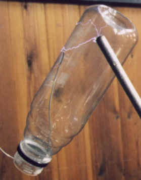
>Discharging through the wall of a plastic drink bottle. If you get the spacing right, the first few shots build up a huge charge on the surfaces of the bottle (you can hear it "sizzling") , and the next one triggers a spectacular flashover.
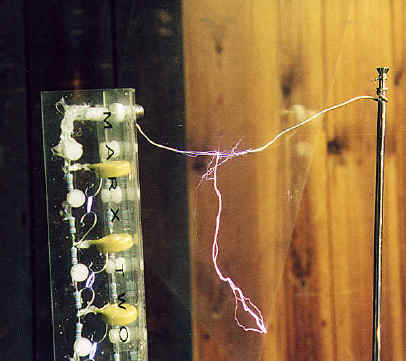
 < Lighting up some argon in a 3 foot plastic tube. Wires were
placed in each end, the ends sealed with parcel tape, and the argon supply turned on for a
few seconds. This photo is a long exposure showing multiple discharges, and looks much
more purple than the real thing, which is an intense white. Each argon fill lasted about
5-10 minutes before a refill was required.
< Lighting up some argon in a 3 foot plastic tube. Wires were
placed in each end, the ends sealed with parcel tape, and the argon supply turned on for a
few seconds. This photo is a long exposure showing multiple discharges, and looks much
more purple than the real thing, which is an intense white. Each argon fill lasted about
5-10 minutes before a refill was required.
"Marx Two-and-a-Half"
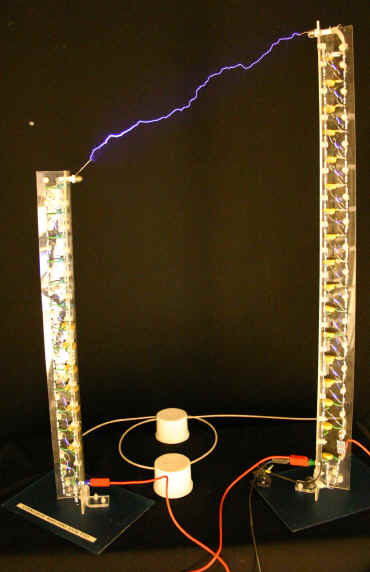
A quick & easy way to improve spark length is to build a second 'Marx two' design, and run them as a pair, in a bipolar configuration. The overall arrangement is effectively the same, except that the input supply is fed to the centre of the bank :
In this configuration, one side generates a high positive voltage, and the other a high negative voltage, giving twice the spark length than a single tower. One advantage of this arrangement is that the voltage to ground at any point is never more than half the total output voltage, reducing corona losses. I built a second bank, consisting of 13 stages (This was simply limited by the size of plastic sheet I had to hand!), and the combined setup will produce sparks about 14" long between the two towers.
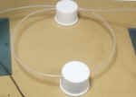 It is very important that the impulse from the gaps firing propagates rapidly
to all stages, and this can cause problems when coupling two towers which are a distance
apart. The main problem is the capacitance to ground of the connection marked
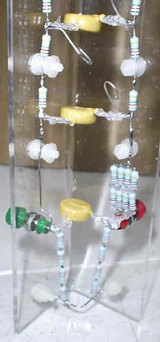
'transmission line' in the above diagram. To reduce this, I used a polythene insulated
wire (from stripped RG58 coax cable), supported by a couple of plastic aerosol can caps
(pictured left) , to ensure that the cable is held at least 40mm from the surface. Coiling
the wire through two caps allows the length to be easily adjusted without the wire curling
down towards the table.
It is very important that the impulse from the gaps firing propagates rapidly
to all stages, and this can cause problems when coupling two towers which are a distance
apart. The main problem is the capacitance to ground of the connection marked
'transmission line' in the above diagram. To reduce this, I used a polythene insulated
wire (from stripped RG58 coax cable), supported by a couple of plastic aerosol can caps
(pictured left) , to ensure that the cable is held at least 40mm from the surface. Coiling
the wire through two caps allows the length to be easily adjusted without the wire curling
down towards the table.
 This image is a long
exposure of several shots, and has been colour-enhanced to show the haze of corona
streamers that can be seen in darkness.
This image is a long
exposure of several shots, and has been colour-enhanced to show the haze of corona
streamers that can be seen in darkness.
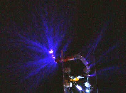 Another enhanced image showing the corona streamers when no output spark
discharge occurs.
Another enhanced image showing the corona streamers when no output spark
discharge occurs.
Power Supply
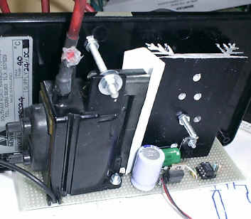
The power supply uses the line output transformer (LOPT) from an old monitor, driven from
an IRF830 high voltage MOSFET and a 555 timer. The frequency used was around 18KHz as this
was the operating frequency of the monitor the transformer came from. You should
experiment with values of C3 and R2 to optimise output for your transformer. C1 and D2
protect Q1 from the high voltage transient from the transformer - C1 is not critical, and
a suitable cap will often be found across the line output transistor in the TV or monitor
that the transformer came from. Q1 should be mounted on a heatsink.
Most LOPTs have an internal rectifier or tripler, and several windings that can be used as
the primary - trial and error is used to determine which set of pins to use (see later).
U2 provides a stable supply for the oscillator as the input voltage is varied to control
the output voltage - the transformer I used would produce up to 25KV from a 20V input at 2
amps. Don't be tempted to go too far over 25KV, as the transformer insulation will
probably break down. It is important to connect the output ground to the input ground or
supply, to avoid the ground side of the HV winding floating to a high voltage which could
break down the insulation.
You want to get the biggest LOPT you can find - the size and power of the LOPT is
usually proportional to screen size, and monitors tend to have bigger ones than TV's of
the same screen size. If you get a LOPT on its own, so can't look at how it was connected
in the monitor, it can be hard to figure out the connections, as the high-voltage
rectifier has a forward voltage too high to test easily. If you have problems figuring out
the pinouts, try this method :
First find a pair of pins that measures a low resistance with a DMM - a an ohm or two. Use
these pins as the primary. Apply power, slowly increasing the voltage until you can draw a
spark between ground and the EHT output. This may be a fairly weak spark as it is only
being coupled via stray capacitance. Then, find the 'HT ground pin(s) by bringing a
grounded wire to within 1mm of each pin in turn - any pin that you can draw a spark from
should be grounded - you may find more than one pin does this, depending on th etripler
configuration. Once these pins are grounded, you should then get a nice juicy spark from
the EHT cap.
If your LOPT has additional high voltage output leads (sometimes marked 'focus' and/or 'Screen), cut them off, and seal the ends of the cut wires with silicone sealant (bathroom sealant).
Another neat very quick & simple way to drive a flyback is to use a halogen lamp
switchmode supply to drive one of the primary windings. Depending on the model of halogen
supply you use, you may be able to adjust the output of this type supply with a standard
light dimmer.
I have subsequently experimented with this, and found that with the halogen supply I had,
it worked better when I connected a capacitor in series with the transformer primary - I
used 1uF and 2.2uF 250V polypropylene types. This allowed the use of an existing winding
on the transformer as the primary. This setup produced over 25KV output very easily, and
the main problem was reducing the voltage - as the mains input voltage (adjusted with a
variac) was increased from zero, it would suddently start at about 16KV with about 50V on
the input - this could be reduced by turning the voltage down afterwards - I think this
effect was caused by the soft-start circuitry in the halogen supply. Experimentation was
curtailed when the the halogen supply died with a fairly spectacular bang. :-(
From the author of the original page I saw this idea on : There is a very
good reason why i used the 210W halogen transformer when making the photoseries for that
page - anything smaller blew up sooner or later, the 210W version was still going strong
till 2 weeks ago when i gutted it for the ferrite core to make a flourescent tube
driver the 210W skott halogen lighting transformer is available from screwfix direct
) for �22.99.
Lessons learnt from this Marx generator to be incorporated into "Marx Three"...:
* Extra insulation is required on the capacitor leads above about 15KV to avoid sparks
jumping across the capacitor leads, and it's a lot easier to put this on BEFORE soldering
everything together! Soft silicone sleeving, or maybe heatshrink would probably be the
best, to avoid small air gaps. Alternatively, the 'V' construction would allow the whole
thing (apart from the spark gaps) to be encapsulated, which would also reduce corona loss,
but require quite a lot of potting compound!
* A method of easily adjusting all of the gaps together would be very useful - for the
next one I think the way to go will be to use two-section gaps, with two, fixed, widely
spaced electrodes, and a set of moveable third electrodes on a hinged support to allow
them all to be moved towards or away from the fixed ones. Dome nuts look like being a
useful cheap source of gap electrodes, with the hexagonal part ground smooth.
* Spark gaps made from wire of this diameter (1mm) are not likely to work well above about
15KV - corona loss makes the breakdown voltage inconsistent.
* 1nF of capacitance per stage is not enough - the spark is not bright & loud enough
at its maximum length - by the time it has crossed the gap, most of the energy has gone. I
think increasing to 5-10nF per stage would make a big difference. Unless I find a cheap
source of HV caps, I'll probably use the MMC approach which has been so successful in
Tesla coils, using series-parallel arrays of caps to increase voltage capability.
* Use a fairly long grounded electrode when experimenting to find maximum spark length, so
fingers are at least 6 inches further away from the output electrode than the ground point
(ouch!).
* A KV meter is a very useful tool when experimenting. I happened to have one, but one
could easily be made using a long string of metal-glaze resistors (taking care to stay
within the voltage rating, to avoid accuracy loss) and a sensitive (50 or 100uA) meter
movement. Calibration from a known HV source should not be necessary - you can check the
meter's FSD current at low voltage against a DMM, and if the resistors are 5%, you should
get 5% overall accuracy. The resistance of the meter can be ignored as it will be way less
than the dropper resistors. For example to make a 100uA meter read 25KV full-scale, the
required resistance would be V/I, i.e. 25E3 / 100E-6 = 250M. Using VR37 resistors, you
want at least ten resistors to keep the voltage across each well within spec, so you could
use sixteen 15M and one 10M in series to give 250M total. For best accuracy, I'd recommend
putting the resistor chain inside a plastic tube, and ideally encapsulating with potting
compound - failure to do this may result in inaccuracy due to corona loss from the solder
joints etc. A possible alternative may be multiple dip-coats in varnish or wax.
Marx Three is now running
Cheap HV Capacitors.
Thanks to Robert Trautman for the following info on home-made capacitors
As you know it's difficult to find inexpensive capacitors of any real
value that'll handle the higher input voltages. I'm using a 25KV flyback transformer
(LOPT) from an old computer monitor as my input, so I needed capacitors that'd handle at
least that voltage.
So, I built my own capacitors using Mylar sheets, normally used as page
protectors in notebooks, and embossing aluminum strips from a craft store. To give them
structure, I rolled these materials (three pieces of Mylar and two aluminum strips,
alternated) around 7/8" (2.2 cm) diameter wooden dowels. In order to achieve the
required voltage rating (I estimate they'll take up to about 50KV), the edges of each
chamfered aluminum strip (capacitor plate) extend no closer to the edges of the Mylar than
about 1.6" (4 cm) all around, thereby allowing 3.2" (8 cm) of distance between
adjacent plates. These materials, once rolled onto a 7/8" (2.2 cm) x 3" (7.6 cm)
dowel produce a 0.005uF (5nF) capacitor at 50KV in a 5.5" (14 cm) x 1" (2.54 cm)
space. The dowel, being made of wood, should be about the same length as the width of the
aluminum strips so as to avoid arcing to this. Obviously, much greater capacitances may be
achieved with longer aluminum strips than those I used, but this was a start.
I built a 10-stage Marx Generator with these homemade capacitors, and they DO work. I am,
however, quite disappointed by the trivial output (only about 7cm). I'd estimated, with
the 25KV input, that I'd get 250KV out. I'm probably losing a lot from corona, despite
significant efforts to minimize it, as I'm only getting around 75KV. Another possible
source of loss could be leakage within these crude capacitors. They work well at storing a
charge, but they may not be the best from a leakage perspective. I may still be able to
get more out of my Marx with more spark-gap tweaking, as, by doing so already, I've
tripled the initial output spark length of 1" (2.54 cm).
I just wanted to pass on to you and those to whom your site might interest that 0.005 microFarad, 50KV capacitors - even if not the most efficient - can be built easily for about $2.00 in materials, each. Again, much larger capacitances may be achieved with longer aluminum strips for the plates. The only problem with longer plates is that another source of the Mylar will have to be found. These notebook sheet protectors provide only around 15.5" (39.4 cm) of useable material per sheet - just enough to accommodate 12" (30.5 cm) long plates with adequate space around them.
Update Oct 2005 - it appears that most of the problem was the power supply, not the capacitors...
![]()
